Introduction
In this tutorial, we are going to implement a “grid-based movement” system for a 2D game in Godot. It’s not overly complex.
Some of you might be wondering, what exactly is grid-based movement? Grid-based movement is when objects, such as characters, move one grid (one tile) at a time on a game screen that is divided into evenly spaced grid lines.
To give some examples, think of older games like the Fire Emblem series, Tactics Ogre, or various simulation games. Even RPGs like Final Fantasy and Dragon Quest during their 2D eras employed grid-based movement when it came to character movement on maps. Puzzle games like Tetris often use grid-based movement for the blocks or pieces as well.
As you can see, grid-based movement is widely used across many genres of games, making it a highly versatile feature.
Environment
This tutorial was created under the following environment:
- Godot version: 4.3
- Computer OS: macOS 14.6.1
By the way, the project I made can be found in this GitHub repository .
Setting Up the Window
After creating a new project in Godot, the first step is to adjust the project settings. Open the Project menu and select Project Settings. From the General tab, navigate to Display > Window in the sidebar, and set the window size and stretch options as follows:
- Size:
- Width: 240
- Height: 176
- Window Width Override: 960
- Window Height Override: 704
- Test Width: 960
- Test Height: 704
- Stretch:
- Mode: viewport
- Aspect: keep
Importing Assets
The assets I used for this project were downloaded from KENNEY’s site. The asset pack I utilized is called 1-Bit Pack . I’m incredibly grateful for these fantastic free resources.
After downloading, I imported the colored-transparent_packed.png file from the Tilesheet folder into the project by dragging and dropping it into the file system dock in the editor.
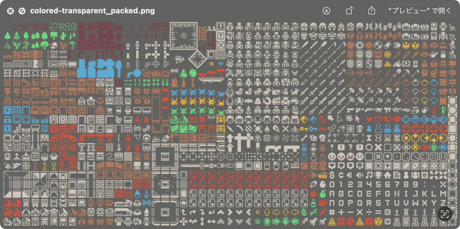
When you first import the file, the image might appear blurry. To fix this, open the Project Settings menu again, go to the General tab, and from the sidebar, select Rendering > Textures. Set the default texture filter to Nearest.
- Canvas Textures
- Default Texture Filter: Nearest
This will give your pixel art that nice, sharp-edged look.
Creating the Game World with TileMap
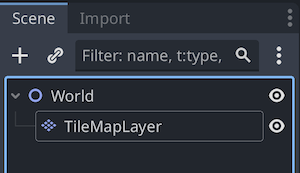
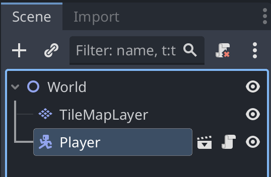
Before we can test grid-based movement, we need to create a background for our player character to move on. So, let’s build the game world using TileMap as the first scene. You might find the following article helpful for creating a TileMap. For this project, I’ve only used one TileMapLayer node.
Reference article: 🤖 Creating TileMaps with TileMapLayer
Here’s how the scene dock looks—simple enough.
Before painting the TileMap, I opened the TileSet editor, went to the Paint tab, and selected Physics > Physics Layer 0 under Paint Properties. I then assigned collision shapes to tiles such as trees and gravestones. This prevents the character from passing through these tiles.
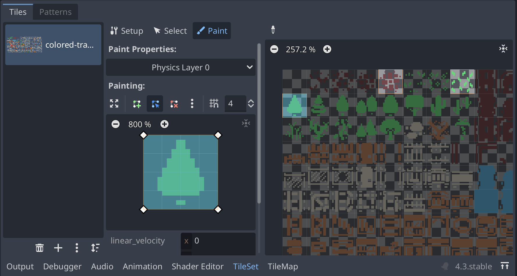
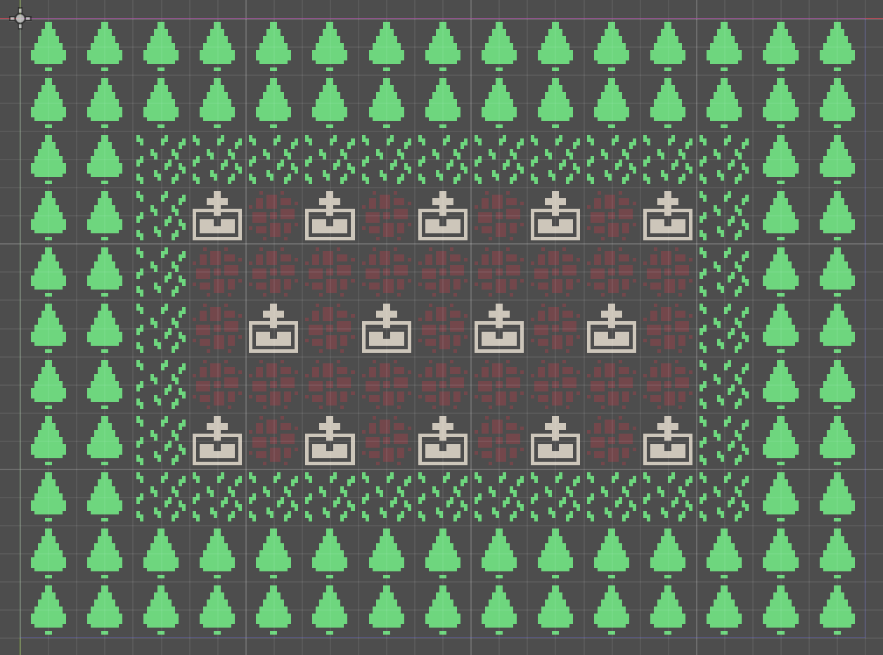
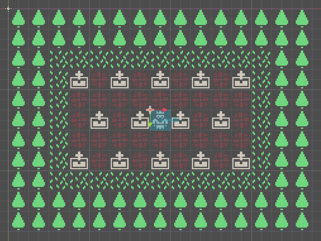
Next, I painted the TileMap in the TileMap editor. Here we have a neatly maintained graveyard.
Creating the Player Character
Now, let’s create the player character’s scene, which will be the object that moves on the grid.
Create a new scene with a CharacterBody2D node as the root node. Rename the root node to “Player”. Then, add the following child nodes to the root node:
- Sprite2D
- CollisionShape2D
- RayCast2D
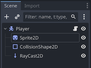
Let’s start editing each node in the Player scene.
Sprite2D Node
Here’s the inspector for the Sprite2D node after editing its properties.
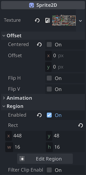
Let’s go over the properties that were modified:
I applied the asset file res://colored-transparent_packed.png to the Texture property in the inspector.
I turned off the Centered property under Offset. This aligns the node’s position to the top-left corner of the texture, making the sprite fit perfectly within one grid square.
I enabled the Region property.
Clicking the Edit Region button opened the Region Editor, where I selected the texture area for the sprite I wanted to use. To make the editing easier, I expanded the panel by clicking the expand icon.

In the panel, I selected Grid Snap mode and set the Step to 16px 16px. This makes the grid size match the size of one sprite texture on the sprite sheet. From here, I selected the texture of the “King” character on the sprite sheet.
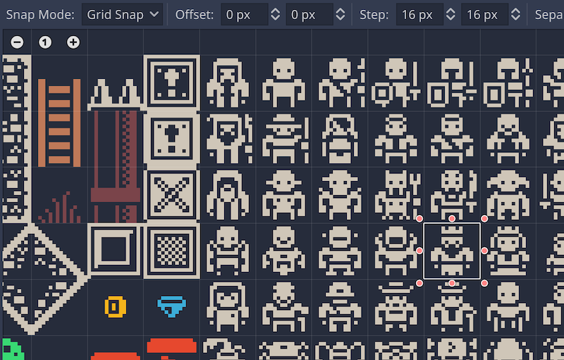
That’s it for editing the Sprite2D node properties.
CollisionShape2D Node
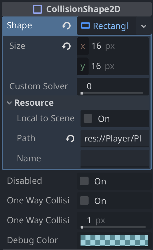
This node will set the collision shape for the CharacterBody2D node (root node). Here’s the inspector after editing.
And this is how it looks in the 2D workspace.

Let’s go over the properties that were adjusted:
I applied a new RectangleShape2D resource to the Shape property.
For the Size of the RectangleShape2D, I set it to (x: 16 px, y: 16 px). You can also visually adjust it in the 2D workspace if needed.
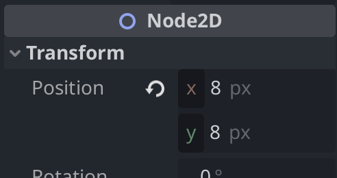
To align with the Sprite2D texture, I set the Position under Transform to (x: 8, y: 8).
RayCast2D Node
The RayCast2D node is very useful for collision detection in grid-based movement. In the 2D workspace, the collision shape is represented as an arrow. The collision is detected when this arrow overlaps with an object. This allows you to control the player character by detecting collisions with objects in front of them and preventing movement beyond certain points. Conversely, without this node, even if collision shapes are set on both the player character and obstacle tiles, the character may pass through the obstacle without collision when moving in a grid-based manner.
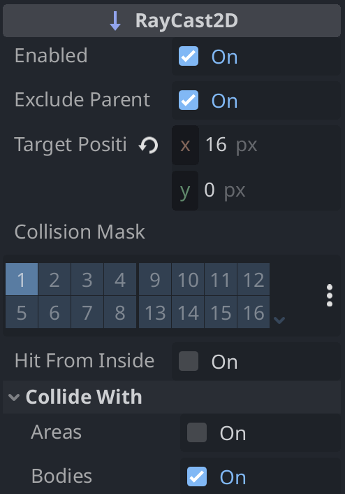
Here’s how the inspector looks after editing.
In the 2D workspace, it looks like this:
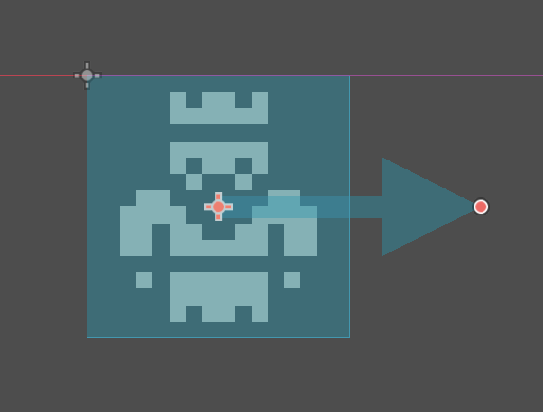
Let’s check each property.
- Leave Enabled set to On (default). This enables collision detection.
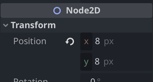
- Set the Transform > Position property to (x: 8, y: 8) to align it with the center of the Sprite2D texture.
- Set the Target Position to (x: 16, y: 0). This is a placeholder initial value, which will be updated in the script according to the player character’s movement.
- Leave Collide With set to Areas as Off and Bodies as On (default). The tiles set in the tileset, like trees and graves, are physical bodies, so collisions will be detected if Bodies is checked.
Implementing Grid-Based Movement in the Player Node
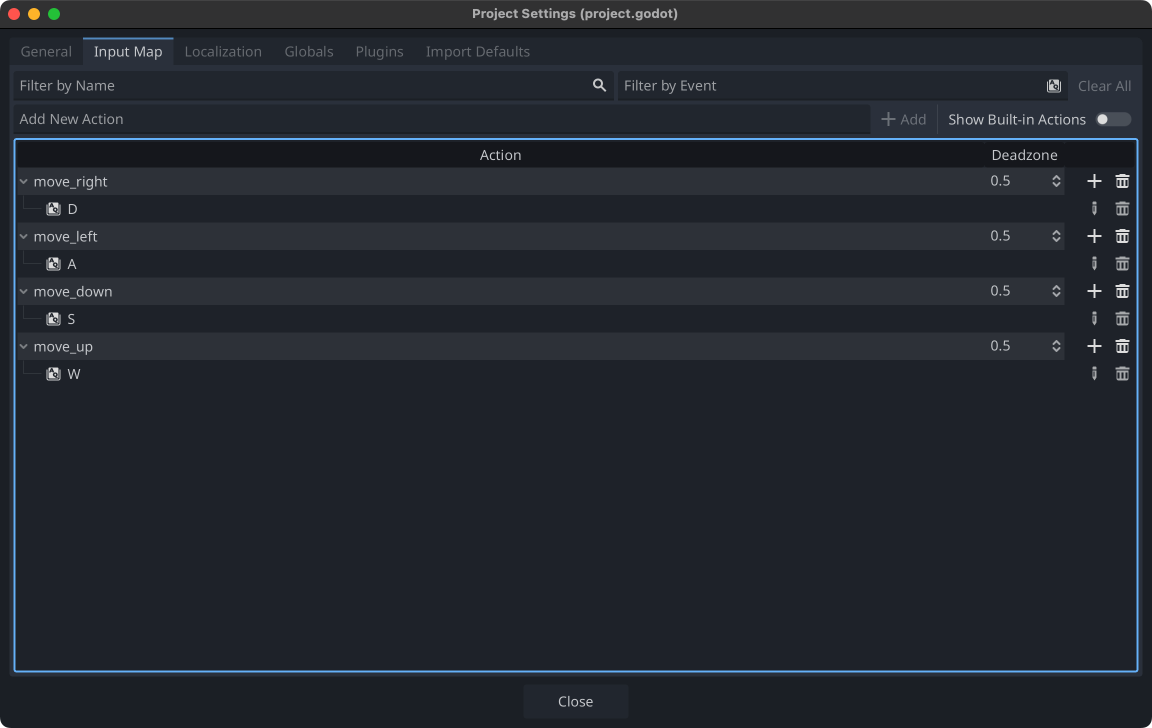
Setting Up the Input Map
To move the player character using keyboard input, first, add actions to the Input Map in the project settings. Select Project menu > Project Settings, open the Input Map tab, and add the following four Actions.
- move_right: D key
- move_left: A key
- move_down: S key
- move_up: W key
Attaching and Editing a Script on the Player Node
Attach a script to the Player (root) node. Here’s the completed code with explanatory comments.
extends CharacterBody2D

# A dictionary that maps input map actions to direction vectors
const inputs = {
    "move_right": Vector2.RIGHT,
    "move_left": Vector2.LEFT,
    "move_down": Vector2.DOWN,
    "move_up": Vector2.UP
}

# Stores the grid size, which is 16 (same as one tile)
var grid_size = 16

# Reference to the RayCast2D node
@onready var ray_cast_2d: RayCast2D = $RayCast2D

# Calls the move function with the appropriate input key
# if any input map action is triggered
func _unhandled_input(event):
    for action in inputs.keys():
        if event.is_action_pressed(action):
            move(action)

# Updates the direction of the RayCast2D according to the input key
# and moves one grid if no collision is detected
func move(action):
    var destination = inputs[action] * grid_size
    ray_cast_2d.target_position = destination
    ray_cast_2d.force_raycast_update()
    if not ray_cast_2d.is_colliding():
        position += destination
This should implement grid-based movement control.
Adding a Player Scene Instance to the World Scene
With the Player scene completed, add an instance node of the Player scene to the World scene.
- Open the World.tscn scene and add an instance node of the Player.tscn scene to the root World node.
- Place the Player node approximately in the center of the 2D workspace (as desired).
Testing Grid-Based Movement
With everything set up, it’s time to test the grid-based movement to ensure everything works as expected.
Pay special attention to how the RayCast2D node detects collisions. If you try to move into a blocked tile (like the trees or graves we set collision shapes for earlier), the player character should stop before crossing into the blocked area.
Run the scene. Your player character should now be able to move smoothly between tiles in a grid-based fashion, and you should be able to control the movement using the keyboard inputs defined in the Input Map.

If everything works correctly, congratulations! You’ve successfully implemented grid-based movement in your 2D game!
Conclusion
In this tutorial, we implemented grid-based movement for a 2D game. It was relatively easy to set up. With further development, you could extend this to automatically move player or enemy characters on a grid. I hope this has been helpful for your game development.
References
- KENNEY
- Godot Docs: Using TileSets
- Godot Docs: Using TileMaps
- Godot Docs: TileSet
- Godot Docs: RayCast2D
- KidsCanCode: Grid-based movement
- YouTube: GDQuest: Grid-based movement Godot 3 demo overview
- YouTube: GDQuest: Exploring grid-based movement
- YouTube: Emi: Make your first 2D grid-based game from scratch in Godot